
一、Arduino与旭日X3派通信
本部分将详细讲解如何通过USB建立Arduino与旭日X3派之间的串口通信,并确保X3派能够成功接收来自Arduino发送的数据。这是实现嵌入式设备联调的基础步骤,适用于各类物联网与机器人项目。
1. 检查X3派上Python是否已安装serial包
在开始通信前,请确认X3派中已安装Python的serial库。若尚未安装,可通过以下命令完成安装:
pip install pyserial
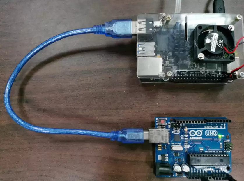
2. 硬件连接:X3派与Arduino通过USB通信
使用标准USB数据线将Arduino开发板连接到X3派的USB接口。连接后,X3派系统会自动识别该设备,无需额外驱动。
3. 验证通信接口:查看设备节点
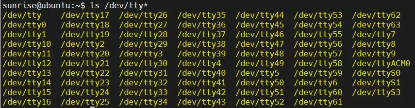
在X3派终端中执行以下命令,观察是否出现 ttyACM0 设备节点。若出现,则说明USB连接正常,通信链路已建立:
ls /dev/tty*如果看到 ttyACM0,说明X3派与Arduino可以正常通信。
4. 在Arduino上烧录测试代码
将以下代码上传至Arduino开发板中。该程序逻辑为:当Arduino收到字符 's' 时,立即返回 "HelloWorld!" 字符串,用于验证双向通信是否正常。
void setup() {
  Serial.begin(9600);
}
void loop() {
  if (Serial.a vailable()) {
    if ('s' == Serial.read())
      Serial.println("HelloWorld!");
  }
}提示:Arduino的串口波特率设置为9600,请确保X3派端使用相同的波特率,否则无法正常解析数据。
5. 在X3派上测试是否收到信息
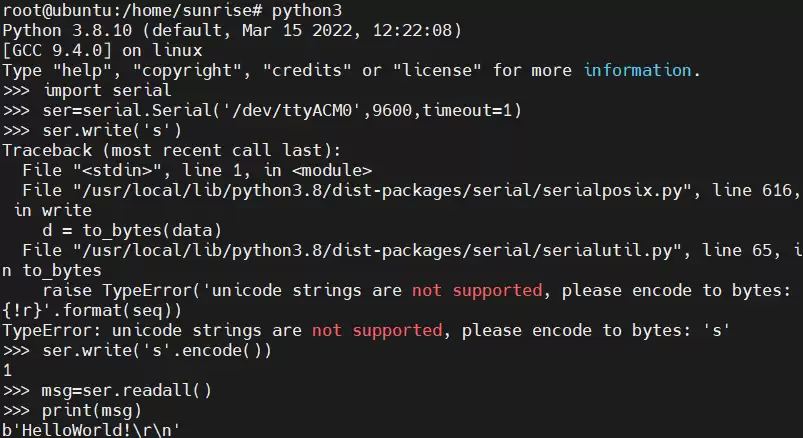
在X3派终端中通过Python3进行测试。创建并运行以下Python脚本,实现向Arduino发送指令并读取返回结果:
import serial
ser = serial.Serial('/dev/ttyACM0', 9600, timeout=1)
while 1:
    ser.write('s'.encode())
    msg = ser.readall()
    print(msg)
运行后,若终端输出显示 HelloWorld!,则说明通信成功,数据交互正常!
注意:在Python中,ser.write('s') 会报编码错误,必须使用 encode() 方法将字符串转换为字节流,如 ser.write('s'.encode())。
6. 权限问题及解决方法
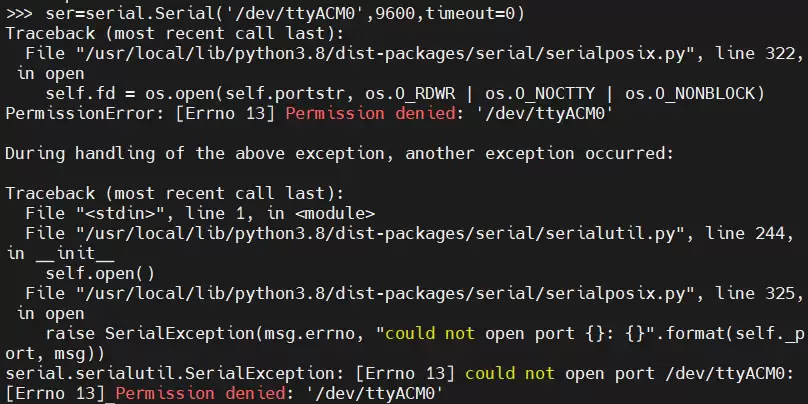
如果运行Python脚本时出现权限错误(如 Permission denied),是因为普通用户没有访问串口设备的权限。请在终端中切换到管理员模式:
sudo su输入密码后,再执行Python脚本即可。
提示:也可以使用 sudo python3 临时提升权限,但建议将用户添加到 dialout 组以永久解决权限问题。
常见问题及解答
- Q:执行
ls /dev/tty*没有看到ttyACM0?
A:请检查USB线是否连接牢固,或尝试更换USB口。如果使用Arduino Nano等板子,可能出现ttyUSB0,需相应调整设备名。 - Q:Arduino代码烧录后,X3派收不到
HelloWorld!?
A:首先确认两边的波特率是否一致(均为9600);其次检查Python脚本中的设备名是否正确,如为ttyUSB0需修改;最后确认Arduino的串口是否被其他程序占用。 - Q:使用
ser.write('s')报错TypeError: 'str' object cannot be interpreted as an integer?
A:串口写入需要字节数据,请使用's'.encode()或b's'。
二、MAX30102人体心率血氧检测模块在上位机旭日X3派上的数据显示
本部分将指导您使用MAX30102传感器采集人体心率与血氧饱和度数据,并通过Arduino发送到X3派进行实时显示与后续分析。该方案适用于健康监测、可穿戴设备原型开发等场景。
1. MAX30102传感器简介
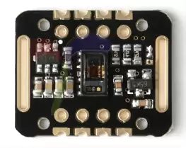
MAX30102是一款高灵敏度脉搏血氧仪和心率传感器,集成完整的信号采集电路,包含光信号发射与接收、模数转换、环境光干扰消除及数字滤波。用户只需通过I2C数字接口即可读取经处理后的数据,广泛应用于智能手环、健康监测贴片等可穿戴设备中。
2. Arduino代码(完整版)
将以下代码上传到Arduino开发板。该代码读取MAX30102的原始数据,并实时计算心率(HR)和血氧饱和度(SpO2),通过串口输出至X3派。
#include
#include "MAX30105.h"
#include "spo2_algorithm.h"

MAX30105 particleSensor;

#define MAX_BRIGHTNESS 255

#if defined(__A VR_ATmega328P__) || defined(__A VR_ATmega168__)
//Arduino Uno doesn't ha ve enough SRAM to store 100 samples of IR led data and red led data in 32-bit format
//To solve this problem, 16-bit MSB of the sampled data will be truncated. Samples become 16-bit data.
uint16_t irBuffer[100]; //infrared LED sensor data
uint16_t redBuffer[100]; //red LED sensor data
#else
uint32_t irBuffer[100]; //infrared LED sensor data
uint32_t redBuffer[100]; //red LED sensor data
#endif

int32_t bufferLength; //data length
int32_t spo2; //SPO2 value
int8_t validSPO2; //indicator to show if the SPO2 calculation is valid
int32_t heartRate; //heart rate value
int8_t validHeartRate; //indicator to show if the heart rate calculation is valid

byte pulseLED = 11; //Must be on PWM pin
byte readLED = 13; //Blinks with each data read

void setup()
{
  Serial.begin(115200); // initialize serial communication at 115200 bits per second:
  pinMode(pulseLED, OUTPUT);
  pinMode(readLED, OUTPUT);
  // Initialize sensor
  if (!particleSensor.begin(Wire, I2C_SPEED_FAST)) //Use default I2C port, 400kHz speed
  {
    Serial.println(F("MAX30105 was not found. Please check wiring/power."));
    while (1);
  }

  byte ledBrightness = 60; //Options: 0=Off to 255=50mA
  byte sampleA verage = 4; //Options: 1, 2, 4, 8, 16, 32
  byte ledMode = 2; //Options: 1 = Red only, 2 = Red + IR, 3 = Red + IR + Green
  byte sampleRate = 100; //Options: 50, 100, 200, 400, 800, 1000, 1600, 3200
  int pulseWidth = 411; //Options: 69, 118, 215, 411
  int adcRange = 4096; //Options: 2048, 4096, 8192, 16384

  particleSensor.setup(ledBrightness, sampleA verage, ledMode, sampleRate, pulseWidth, adcRange); //Configure sensor with these settings
}

void loop()
{
  bufferLength = 100; //buffer length of 100 stores 4 seconds of samples running at 25sps

  //read the first 100 samples, and determine the signal range
  for (byte i = 0 ; i < bufferLength ; i++)
  {
    while (particleSensor.a vailable() == false) //do we ha ve new data?
      particleSensor.check(); //Check the sensor for new data

    redBuffer[i] = particleSensor.getRed();
    irBuffer[i] = particleSensor.getIR();
    particleSensor.nextSample(); //We're finished with this sample so move to next sample

    Serial.print(F("red="));
    Serial.print(redBuffer[i], DEC);
    Serial.print(F(", ir="));
    Serial.println(irBuffer[i], DEC);
  }

  //calculate heart rate and SpO2 after first 100 samples (first 4 seconds of samples)
  maxim_heart_rate_and_oxygen_saturation(irBuffer, bufferLength, redBuffer, &spo2, &validSPO2, &heartRate, &validHeartRate);

  //Continuously taking samples from MAX30102. Heart rate and SpO2 are calculated every 1 second
  while (1)
  {
    //dumping the first 25 sets of samples in the memory and shift the last 75 sets of samples to the top
    for (byte i = 25; i < 100; i++)
    {
      redBuffer[i - 25] = redBuffer[i];
      irBuffer[i - 25] = irBuffer[i];
    }

    //take 25 sets of samples before calculating the heart rate.
    for (byte i = 75; i < 100; i++)
    {
      while (particleSensor.a vailable() == false) //do we ha ve new data?
        particleSensor.check(); //Check the sensor for new data

      digitalWrite(readLED, !digitalRead(readLED)); //Blink onboard LED with every data read

      redBuffer[i] = particleSensor.getRed();
      irBuffer[i] = particleSensor.getIR();
      particleSensor.nextSample(); //We're finished with this sample so move to next sample

      //send samples and calculation result to terminal program through UART
      Serial.print(F(", HR="));
      Serial.print(heartRate, DEC);
      Serial.print(F(", SPO2="));
      Serial.println(spo2, DEC);
    }

    //After gathering 25 new samples recalculate HR and SP02
    maxim_heart_rate_and_oxygen_saturation(irBuffer, bufferLength, redBuffer, &spo2, &validSPO2, &heartRate, &validHeartRate);
  }
} 注意:该代码依赖
MAX30105库和spo2_algorithm库,请先在Arduino IDE中安装 SparkFun MAX3010x Pulse and Proximity Sensor Library。
3. 硬件接线
将MAX30102模块与Arduino按照下表连接,确保供电和I2C通信线路正确:
- VCC → 5V
- GND → GND
- SCL → A5
- SDA → A4
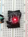
建议:用绝缘黑胶布将MAX30102模块周围(包括金属部分)包裹起来,避免手指触碰电阻对环境光产生干扰,影响测量结果。
4. X3派上接收数据的Python代码
在X3派终端中创建一个Python脚本,用于接收Arduino发送的心率血氧数据。使用以下命令新建文件:
sudo nano max30102_test.py输入以下内容:
import serial
ser = serial.Serial('/dev/ttyACM0', 115200, timeout=1)
while 1:
    msg = ser.read(10)
print(msg)注意:Arduino的串口波特率设置为115200,此处必须保持一致,否则无法正确解析数据流。
5. 运行测试
在终端中执行Python脚本:
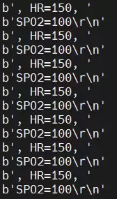
python3 max30102_test.py将手指轻轻放在MAX30102传感器上(不要按压过重)。等待几秒后,终端会显示心率(HR)和血氧(SPO2)数据。
- 心率数据通常较快得出,血氧数据需要等待较长时间(约30秒至1分钟)才能稳定。
- 输出中
HR为心率,SPO2为血氧饱和度,ir和red为中间计算值。
常见问题及解答
- Q:Arduino上电后,串口输出显示
MAX30105 was not found?
A:请检查接线是否正确,尤其是VCC(5V)、GND、SCL(A5)、SDA(A4)是否连接牢固。另外,MAX30102模块的供电电压为5V,不要使用3.3V。 - Q:X3派终端输出乱码或没有数据?
A:首先确认Arduino的波特率是115200,Python脚本中设置的是115200。如果仍然乱码,检查Arduino代码中是否开启了其他串口输出(如打印原始数据),可能会干扰心率血氧的解析输出。 - Q:血氧值一直显示0或异常值?
A:血氧测量需要传感器稳定贴合手指,且需要一定时间(约30秒以上)的算法收敛。请确保手指按压力度适中,避免晃动。同时,检查环境光是否过强,可用黑胶布遮挡传感器侧面。 - Q:为什么读取到的数据只有
HR和SPO2,没有ir和red?
A:Arduino代码在循环中只打印了HR和SPO2,原始数据(ir/red)仅在初始化阶段打印。如需查看原始数据,可以在循环中增加打印语句。
本文转自地平线开发者社区
原作者:jmulin
原链接:https://developer.horizon.ai/forumDetail/98129540173361549