点胶质量检测实战教程:从检测原理到Halcon代码全解析
在工业视觉检测与自动化质检领域,点胶质量的精准把控始终是核心环节。胶路是否连续无断点、宽度是否均匀一致、位置有无偏移,直接决定了产品的密封性能与结构强度,进而影响良品率。
本文围绕一个典型的Halcon示例程序——apply_bead_inspection_model.hdev,系统拆解点胶检测的核心思路与代码实现细节,帮助工程师快速掌握视觉点胶检测的落地方法。
点胶检测任务:明确常见缺陷类型
点胶质量检测主要针对以下三类常见缺陷:
- 断胶:胶路出现不连续区域,导致粘合胶缺失,影响密封性。
- 溢胶或缺胶:粘合剂的涂布量超出或低于公差范围,表现为胶路过宽或过窄。
- 点胶偏移:实际胶路偏离预设路径过远,造成位置偏差。
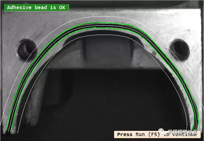
以下为典型缺陷的效果图:
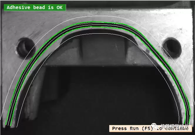
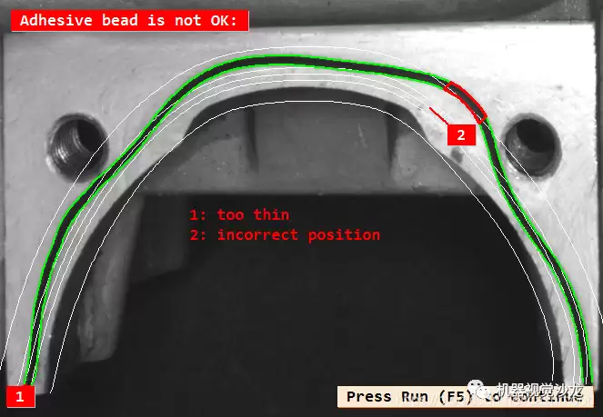
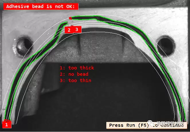
检测思路:从图像预处理到缺陷判别
该示例程序的图像处理流程逻辑清晰,主要分为以下几个关键步骤:
1. 使用可变形模板匹配将工件校正至标准位姿
在实际产线中,这一步并非必须采用可变形匹配;通过常规模板匹配配合2D仿射变换,通常已能保证图像采集的一致性。具体选用哪种方式需根据工况灵活决定。
2. 定义粘合胶条的参考路径、标准宽度及误差容忍值
官方示例直接给出了轨迹点集。但在真实检测项目里,可通过导入CAD图纸或手动绘制路径(如使用draw_nurbs)完成。参考路径的准确性是所有后续判定的基准。
3. 利用算子 create_bead_inspection_model 创建点胶检测模型
这一步类似于模板匹配中的create_shape_model,将参考路径、宽度及公差参数打包成一个可复用的检测模型,方便后续批量调用。
4. 校正胶路位置,生成并显示四条平行轮廓
此步主要将参考路径、标准宽度边界和位置公差范围可视化,便于调试阶段确认参数设置是否正确。
5. 读入待检测图像并校正,调用 apply_bead_inspection_model 执行检测
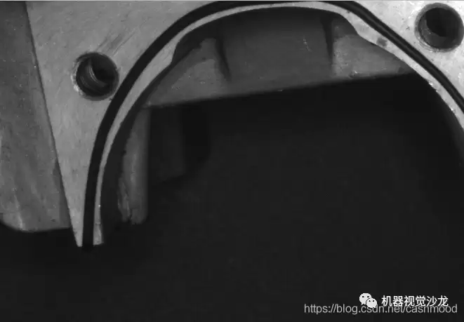
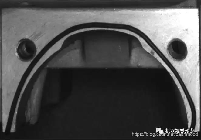
从这一步开始进入正式检测。先通过仿射变换将图像转正,确保每张待测图片的处理区域一致,大幅降低后续算法难度。然后一行代码完成检测,逻辑简洁高效。
6. 根据检测类型在窗口上显示结果
最后将检测结果可视化:OK或NG,缺陷具体位置与类型一目了然,便于现场人员快速响应。
点胶质量检测代码详解:每一步的实战意义
本例中图像矫正采用平面可变形匹配。首先关闭窗口更新以提升界面流畅度。
dev_update_off ()
随后用仿射变换将图像转正,并创建平面可变形模板。核心目的是保障每张待测图片的空间一致性。
prepare_alignment (RegionPart, RowT, ColumnT, ModelID)
求取检测区域的最小外接矩形,仅对相关区域处理,有效提升算法运算速度。
smallest_rectangle1 (RegionPart, PartRow1, PartColumn1, PartRow2, PartColumn2)
定义点胶轨迹的参考路径。官方示例使用轨迹点集,实际项目中也可通过draw_nurbs在参考图像上交互式绘制生成。
gen_contour_nurbs_xld (ContourRef, [701.767,626.953,538.867,443.54,390.447,360.28,354.247,363.9,400.1,458.02,509.907,588.34,659.533,696.94], [319.24,336.133,367.507,431.46,489.38,546.093,646.247,722.267,776.567,826.04,869.48,912.92,934.64,929.813], ‘auto’, [15,15,15,15,15,15,15,15,15,15,15,15,15,15], 3, 1, 5)
下面定义模型的关键参数:标准宽度、宽度公差、位置公差以及胶路极性(亮胶还是暗胶)。
TargetWidth := 14WidthTolerance := 7PositionTolerance := 30Polarity := ‘dark’
创建点胶轨迹检测模板。create_bead_inspection_model接收参考轮廓、标准宽度、宽度公差、位置公差、极性以及两个空数组(sigma和阈值),输出模型句柄。
create_bead_inspection_model (ContourRef, TargetWidth, WidthTolerance, PositionTolerance, Polarity, [], [], BeadInspectionModel)
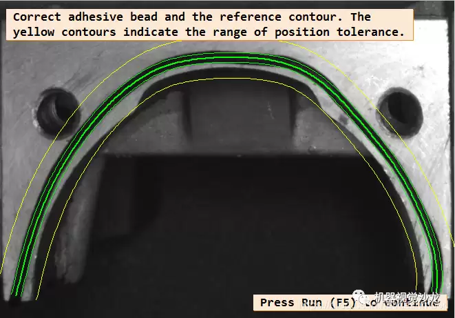
读入第一张参考图片,校正后显示点胶轨迹及相关描述信息。
read_image (Image, ‘bead/adhesive_bead_01’)align_bead (Image, ImageAligned, ModelID, RowT, ColumnT)
生成两条平行轮廓,分别对应标准宽度边界和位置公差边界,用于可视化调试。
gen_parallel_contour_xld (ContourRef, ModelSide1, ‘regression_normal’, TargetWidth * 0.5)gen_parallel_contour_xld (ContourRef, ModelSide2, ‘regression_normal’, -TargetWidth * 0.5)concat_obj (ModelSide1, ModelSide2, ModelSides)
gen_parallel_contour_xld (ContourRef, PositionToleranceSide1, ‘regression_normal’, PositionTolerance)gen_parallel_contour_xld (ContourRef, PositionToleranceSide2, ‘regression_normal’, -PositionTolerance)concat_obj (PositionToleranceSide1, PositionToleranceSide2, PositionToleranceSides)
随后进行窗口显示相关操作:设置字体、显示参考轮廓、标准宽度边界和容许范围,并给出文字提示。
dev_close_window ()
dev_open_window_fit_size (0, 0, PartColumn2 - PartColumn1 + 1, PartRow2 - PartRow1 + 41, -1, -1, WindowHandle)
set_display_font (WindowHandle, 16, ‘mono’, ‘true’, ‘false’)
dev_set_part (PartRow1 - 20, PartColumn1, PartRow2 + 20, PartColumn2)
dev_display (ImageAligned)
dev_set_line_width (2)
dev_set_color (‘green’)
dev_display (ContourRef) //粘合胶条的参考路径
dev_set_line_width (1)
dev_display (ModelSides) //胶条的宽度
dev_set_color (‘yellow’)
dev_display (PositionToleranceSides) //容许点胶范围
显示描述文本后暂停,等待用户确认。
Message := ‘Correct adhesive bead and the reference contour. The’Message[1] := ‘yellow contours indicate the range of position tolerance.’disp_message (WindowHandle, Message, ‘window’, 12, 12, ‘black’, ‘true’)disp_continue_message (WindowHandle, ‘black’, ‘true’)stop ()
批量检测:循环读入图片并调用模型
接下来进入循环检测环节。一共7张测试图,依次读入、校正、调用检测模型,输出结果。
TextOffset := 20NumImages := 7for Index := 1 to NumImages by 1read_image (Image, ‘bead/adhesive_bead_’ + Index$‘02’)align_bead (Image, ImageAligned, ModelID, RowT, ColumnT)
核心检测算子apply_bead_inspection_model会输出左轮廓、右轮廓、缺陷段以及缺陷类型。
apply_bead_inspection_model (ImageAligned, LeftContour, RightContour, ErrorSegment, BeadInspectionModel, ErrorType)
接着进行显示与逻辑判断:若ErrorType为空则显示OK;否则根据缺陷类别(no bead、too thin、too thick、incorrect position)用红色标注缺陷区域,并编号显示。
if (|ErrorType| == 0)Message := ‘Adhesive bead is OK’disp_message (WindowHandle, Message, ‘window’, 12, 12, ‘white’, ‘forest green’)disp_continue_message (WindowHandle, ‘black’, ‘true’)stop ()elseMessage[0] := ‘Adhesive bead is not OK:’ErrorClasses := [‘no bead’,‘too thin’,‘too thick’,‘incorrect position’]for ClassIndex := 0 to |ErrorClasses| - 1 by 1Class := ErrorClasses[ClassIndex]ErrorIndices := find(ErrorType,Class)if (ErrorIndices != -1)select_obj (ErrorSegment, SelectedSegments, ErrorIndices + 1)dev_set_color (‘red’)dev_set_line_width (3)if (Class != ‘no bead’)gen_display_segments (SelectedSegments, LeftContour, RightContour, ErrorParts)dev_display (ErrorParts)elsedev_display (SelectedSegments)endifarea_center_points_xld (SelectedSegments, Area, Row, Column)for E := 0 to |ErrorIndices| - 1 by 1disp_message (WindowHandle, ErrorIndices[E] + 1, ‘image’, Row[E], Column[E] - TextOffset, ‘white’, ‘red’)TextOffset := 20 - TextOffsetendforendifendfordisp_message (WindowHandle, Message, ‘window’, 12, 12, ‘white’, ‘red’)disp_message (WindowHandle, [1:|ErrorType|] + ': ’ + ErrorType, ‘image’, 500, 500, ‘red’, ‘false’)if (Index < NumImages)disp_continue_message (WindowHandle, ‘black’, ‘true’)stop ()endifendifendfor
循环结束后释放所有模板句柄,做好资源清理。
clear_bead_inspection_model (BeadInspectionModel)clear_deformable_model (ModelID)
完整流程示意图:从模板创建到结果输出
1. 使用符合要求的合格图像创建检测模板
2. 读入新图像,通过仿射变换进行矫正
矫正前图像:
矫正后图像:
3. 使用已创建的模板检测点胶轨迹,输出缺陷结果